Year-end offer: Save 50% on Able2Extract Professional single license purchases before December 31!

How To Align And Scale Objects Simultaneously?

Part 6 of 13 in our How To Use AutoCAD series

As you know, AutoCAD is all about creating accurate drawings. So being able to adjust and fine tune the placement and size of your objects accordingly is a necessary skill to have.  Whether you need to  resize your objects or move them around, you need to be able to manipulate your drawings accurately and with efficiency. That’s why it’s important to master the Align tool early on.

Here’s how to align and scale objects at the same time:

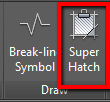
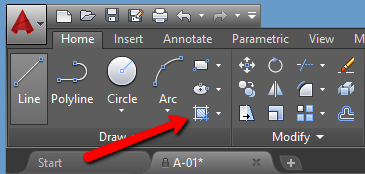
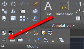
1. Identify which objects you would like to align. Go to the Modify panel, click on the drop down arrow and select the “Align” tool, located on the bottom left side.

Locating AutoCAD Align Tool

2. Select the object that you wish to align and hit “Enter”.

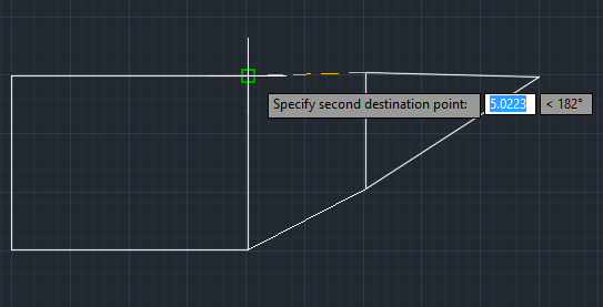
3. Select the source point. The source point is a part of the object that you align (for example, its edge, side or center). After doing so, specify the destination point of the alignment. The destination point represents a point to which you align your selected object. Hit “Enter” and specify the second source and destination point.

Specifying Second Destination Point

4. Either right click on the drawing window or press “Enter”. You’ll be prompted on whether you want to “Scale objects based on alignment points?” or not. If you’d like AutoCAD to automatically scale the selected object to fit your destination object, click Yes. Otherwise, click No.

Once you get the hang of it, this method will come as second nature. Mastering this tool is great skill to have under your belt. Not only does it allow you to quickly edit CAD designs accordingly, but it’ll also give you a better sense of how AutoCAD professionals work with the application.

How To Create Custom Hatch Patterns?

Part 5 of 13 in our How To Use AutoCAD series

One of the great things about AutoCAD is that it can be used to design drawings meant for different types of industries. And because AutoCAD designs can be intended for any structure under the sun, the material being used or involved in the design’s construction can vary greatly.  

This poses an interesting situation when AutoCAD users need to fill in the hatches of their drawings. These hatches represent the real material to be used. So getting the hatch patterns just as accurate as the drawings themselves is important.

Now, although AutoCAD offers plenty of hatch patterns on its own, sometimes we may want to personalize our drawings and implement our own hatch patterns. You can do this by following these simple steps:

1.In your AutoCAD document, draw a desired pattern using a tool from the Draw panel.

2. In the Block panel, click on the “Create” command, located in the top right corner.

Selecting Create Block Option

3. Name your pattern and click “OK”. On the pop-up, choose “Select objects”.

4. Click on your drawing until it gets light blue, and hit Enter.

5. Now select “Pick point” and place the cursor on the bottom left corner of your pattern drawing.

Selecting Pick Point Option

6. Hit “OK”.

7. Go to the “Express Tools” tab > Draw panel > Super Hatch.

Selecting Super Hatch

8. Choose “Block” as your desired pattern type, select your block by name and hit “OK”.

Selecting Hatch Pattern

9. Fit your pattern by following instructions. When you’re satisfied hit Enter.

10. Click on the desired area that you want to hatch and once selected, hit Enter.

All done! For advanced users who are interested in more hatch pattern customization options, check out this tutorial from Ellen Finkelstein.

How To Hatch Or Fill Objects/Areas?

Part 4 of 13 in our How To Use AutoCAD series

When using AutoCAD to draft blueprints or designs, the CAD designer must keep in mind the type of material that will be used when the design is built.  For this, AutoCAD uses “hatches” that represent solid masses and materials to be used and incorporated within the design when it’s built.

When creating your CAD drawing, you can decide on the pattern to be used to represent the material intended to be used during construction with AutoCAD’s hatch command.   

The hatch command in AutoCAD is used to fill an area or selected objects with a hatch pattern or a fill. Here’s how to use the command in a few simple steps:

1.Go to the Draw panel on the Home tab. Find the hatch icon in the bottom right corner.

Using Autocad Hatch Command

2. You will see a “Hatch creation” tab. Go to its Properties panel and choose the Hatch type that you would like to insert. Choose between Solid, Gradient, Pattern or User Defined.

3. Further specify the pattern on the Pattern panel.

Pattern Hatch Type

4. Choose your desired method: “Pick Points” or “Select Boundary Objects”. The “Pick Points” will determine a boundary around the specified point. The “Select Boundary Objects” will allow you to manually select the boundaries of the area that you would like to hatch.

5. After filling the area, hit “Enter” to apply the hatch.

As you can see, when using AutoCAD for any design, being as detailed as possible is not only essential, but easy when it comes to specifying small details such as construction material.

How To Scale Objects With A Reference?

Creating CAD Drawing

Part 3 of 13 in our How To Use AutoCAD series

For AutoCAD users, being able to resize and scale a design is crucial. It can mean the difference between a successful project and a disastrous design. This is why AutoCAD comes equipped with a ton of advanced features to make scaling designs an easy task. 

As a matter of fact, AutoCAD will go so far as to allow you to scale objects by factor or reference using the Scale command. Changing the size of objects by reference is based on the existing distance for specifying the new size of your object.

Here’s how to scale objects with a reference in AutoCAD 2016:

  1. Select the Scale command.
  2. Select the desired object.
  3. Specify the current distance.
  4. Specify the new intended size.

It’s also possible to scale the entire drawing by Reference, not only individual objects. To do that:

  1. Select all objects in the drawing.
  2. Using Reference, select two points.
  3. Specify the desired distance to scale all the objects in the drawing accordingly.

Scaling objects is a detailed oriented task that may seem tedious at first, but with the Scale command, you can master the task in as little as 4 steps.

How To Export A Table From PDF AutoCAD Drawing Into Excel?

Part 2 of 13 in our How To Use AutoCAD series

Working with PDF documents is difficult. Just working with the data itself can be time consuming. This is especially true when you need to extract something as precise as a PDF table into Excel. It requires that data to be transferred, cell by cell correctly into a spreadsheet, formatted perfectly and faithfully to the original.

So you can imagine how exporting a table from a PDF drawing to Excel is somewhat more complicated than exporting a table straight from AutoCAD to Excel.

However, this can be easily accomplished with Able2Extract’s “Custom PDF to Excel” conversion feature.

You can download the 7 day free trial and follow the steps below to export your table.

1.Open your PDF drawing with Able2Extract.

2. In the select panel, click on “Area”. Left click and drag to mark the table that you would like to export.

Selecting PDF Drawing Content

3. Once selected, click on “Excel”.

4. You’ll be presented with a Convert to Excel panel. Export simple tables automatically by clicking “Convert”. For now, stick to the Custom conversion and hit “Define”.

PDF Drawing Table Conversion

5. Now you have a complete control over your PDF to Excel conversion. Use the toolbar on the right to add and remove output columns and rows. When satisfied, check the “Show Preview” box to review your results.

6. Click “Convert” and save the file.

PDF To Excel Results

Converting AutoCAD tables to Excel may sound like a complicated procedure at first, but with the right tool, you can easily maneuver around that obstacle and work with any AutoCAD tables you come across.