Although AutoCAD is a complex program that brings to mind computer experts and technical precision, it’s an application that, despite its intimidating nature, can be very rewarding once you learn about it.
If you’re interested in AutoCAD, you’re probably full of questions. Well, we’ve scoured the web for the most common FAQs about AutoCAD usage and best industry practices and found the answers to them. Whether you’re a newbie, a hobbyist or an existing AutoCAD user, you’ll get one super AutoCAD knowledge source right at your fingertips.
Check it out. After all, if someone had a question about the program, chances are you have the same one too!
What Projects Can Be Done In AutoCAD?
Autodesk AutoCAD is a general purpose CAD software application. As such, it can be used for drafting and design projects that involve creation, editing, viewing or printing various types of geometric 2D and 3D entities. Basically, this includes various projects in areas of architectural, civil, mechanical or electrical engineering drawing and design.
Do Civil Engineers Need To Learn AutoCAD?
The general consensus among experts online is that civil engineers do need to know their way around CAD software. According to many structural engineers, like Norbert Pozsonyi at Quora, AutoDesk’s AutoCAD is an essential CAD software tool to learn and know. Learning AutoCAD will at least help you to read drawings, which is of vital importance for civil engineers.
Whether and how much you will really need it in practice, depends on where you are (in which part of the world) and what software is used at the company you work for.
What CAD Software Does A Civil Engineer Need To Know To Land A Job?
Autodesk’s AutoCAD is an industry standard used by the vast majority of civil engineers and construction firms, but there are still many others that use different CAD software. So, if you have to pick one CAD software to learn, choose AutoCAD. But, to improve your prospects of landing a job as a civil engineer, you may want to learn a few other CAD software applications. Some of the most commonly used ones that will add extra strings to any civil engineer’s bow include MicroStation, Revit and Tekla. A comprehensive list of CAD editors and a comparison of computer-aided design solutions is available at Wikipedia.
What Is The Difference Between AutoCAD And AutoCAD 360?
AutoCAD is a commercial computer-aided design (CAD) desktop software application for 2D and 3D design and drafting. It’s used for creating blueprints and other engineering plans. AutoCAD is mostly used by drafters in architectural drafting, civil drafting, mechanical drafting, electrical drafting, electronics, aeronautical drafting, and beyond.
AutoCAD is available for Microsoft Windows and Mac OS X.
AutoCAD 360, on the other hand, is a web and mobile drawing and drafting application that allows registered users to view, edit and share AutoCAD drawings via web and mobile devices. AutoCAD 360 is used by general contractors, project managers and tradesman with little to no experience with CAD and is commonly used across a wide range of industries: architecture, engineering and construction, mechanical, electrical, plumbing, and more.
AutoCAD 360 is available for download as a mobile app for Android and iOS devices.
What Is The Difference Between AutoCAD And Solidworks?
A CAD analyst Sandeep Kumar summed it up on Quora: Autodesk’s AutoCAD was initially designed for 2D drafting and subsequently extended with some 3D features. SolidWorks, on the other hand, is a full featured 3D modelling CAD software.

When it comes to 3D modelling, SolidWorks is for the advanced users and tasks, while AutoCAD is mainly for intermediate 3D modelling.
However, while AutoCAD is available for both Microsoft Windows and Mac OS, Solidworks runs exclusively on Microsoft Windows OS.
Autodesk’s Inventor is actually Solidworks’ counterpart, rather than the often compared AutoCAD
What Are The Differences Between AutoCAD, AutoCAD Architecture, 3DS Max And Revit?
AutoCAD is, as already mentioned above, primarily a 2D drafting software with moderate 3D modelling capabilities. It uses lines to graphically represent objects.
AutoCAD Architecture is a specialized version of AutoCAD with additional tools designed specifically for architects to enhance their workflow, aiding in tasks such as architectural planning and construction documentation.
Revit is a 4D BIM modeling software with tools for planning and tracking various stages in a building’s lifecycle, from concept to construction and eventual demolition. Simply said, Revit is used for building computer models of physical structures. It allows users to create actual objects with attached parameters and data like material, as opposed to just creating lines that graphically represent objects. It should be noted that Revit is a building modelling tool, and isn’t used for generic modelling purposes.
Autodesk 3ds Max is a 3D modelling, animation and rendering software. It’s mostly used for making 3D animations, games, images, movie effects and movie-pre-visualization. Its most common users are video game developers, TV studios and architectural visualization studios. While AutoCAD is primarily used for drafting, 3ds Max is mostly used for presentation. These two are both are geometric modellers, while AutoCAD Architecture and Revit are classified as BIM modellers.
Despite the differences between them, these programs primarily handle design and its implementation into usable construction and presentation documents.
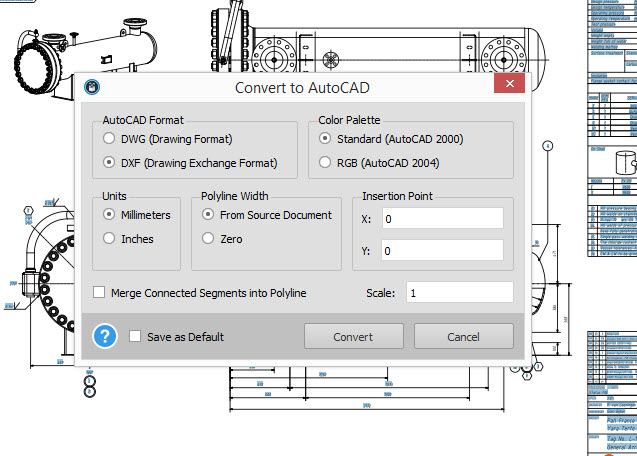
What Are The Limitations Of AutoCAD Supported .DXF File Format?
To identify limitations or advantages of the .DXF file format, it is necessary to compare it to AutoCAD’s native .DWG format. What can these formats do and which should you use?
Although both file formats are developed by Autodesk and supported by AutoCAD, there are some differences between the two vector image file types. The main one is that DWG (which stands for DraWinG) files only work with Autodesk’s AutoCAD, while .DXF (meaning drawing exchange/interchange format) was developed to allow other CAD programs to open and use information from the drawing file.
Furthermore, some CAD programs can’t import .DWG files, but they can import .DXF. That being said, if you’re a CAD user who doesn’t use AutoCAD, the ability to open and use the .DXF file in other CAD programs is its obvious advantage over the DWG.
Possible limitations of .DXF in comparison to DWG are:
- DWG files retain all drawing layers, colors, lines weights and x-references, while DXF files retain lines, dimension and text only.
- While DXF is ACSII text, DWG is a binary file. This means that .DXF is more bloated in size than DWG.
Despite these potential drawbacks, the ability to work with all vector-based programs has made the .DXF the most pervasive vector file type in the CAD industry.
Is It Possible To Convert TIFF To AutoCAD File?
It isn’t possible to directly convert TIFF image to DWG/DXF, but there’s a workaround you can try if you need to reuse a TIFF image in AutoCAD. Use the IMAGEATTACH command to insert TIFF as a raster image, then use the image as reference. It’s possible to trace the image.
Is It Possible To Convert PDF To CAD File?
Yes, it’s possible to convert PDF to CAD file. All you need is a PDF to CAD conversion solution. There are a number of available PDF to CAD converters, including Investintech’s Able2Extract, which converts PDF to DWG and DXF formats. Able2Extract PDF Converter is a desktop software, which is free to try for 7 days. There are also some free online PDF to AutoCAD converters, like this one.
If the PDF file was generated from a CAD application, such as AutoCAD, the vector data should be embedded in it, which allows for an easy and accurate conversion.
Do Software Packages That Convert PDF To CAD Files Really Work?
In short: yes, they work. According to a BIM expert and educator, Stefan Boeykens, there are a number of things to keep in mind when converting and evaluating results of a PDF to CAD conversion. Firstly, note that a PDF file is a visual representation of a CAD drawing. It contains lines, color and text. Thus, when it comes to the conversion output of such files, know that:
- Lines are, by rule, converted accurately, with an exception to line weights which convert with less accuracy.
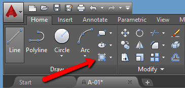
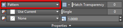
- Hatches are turned into blocks or groups of lines.
- With text and dimensions, the conversion output largely depends on the source. Thus, text can be turned into curves resembling the text, and dimensions become grouped text and lines. There can’t be dimension entity in the conversion output simply because there is no such thing in the PDF.
Note that when converting PDF to CAD drawings, your resulting content will end up as a graphical output containing line-properties, colors, curves, etc.
What Is The Best Format To Transfer CAD Files To Non-CAD Recipients?
The default and usually the best format for non-CAD recipients is the PDF (Portable Document format) as anyone can open and view PDFs on any device. PDFs are non-editable and an obvious choice when the owner or sender doesn’t want the recipient to edit the document.
An alternative to PDF would be DWF as another non-editable file format. However, to open it, the recipient needs to have DWF viewer installed. Compared to the widely used PDF format and the number of freely available PDF readers, chances are that most non-CAD users won’t have the necessary DWF viewers installed on their devices. They may even be unaware of such software, or even if they are, finding and installing would take up extra time.
If you want to transfer the editable CAD file to a client, project manager, tradesman, contractor or any other project stakeholder, the best formats are .DWG or .DXF. If they don’t generally use desktop AutoCAD, they can open the DWG or the DXF files in AutoCAD 360 even with a free plan and make edits to it.