How To Insert A Title Block?

Part 13 of 13 in our How To Use AutoCAD series

Because AutoCAD projects are highly detailed and require accuracy, being organized with how you work is important. Imagine dealing with a dozen CAD design files with detailed information outlining a single part. If you aren’t organized in how you label each drawing for printing, then recipients won’t have the necessary information for them.

This is why inserting a Title Block in your AutoCAD drawing is essential for plotting (printing) your drawings, especially in a production environment. A Title Block is used to name the drawing part, time and author. Essentially, it provides important information for when the document is printed.

Creating AutoCAD Title Block

In AutoCAD, you can create your own Title Block template or import a premade template.  To insert a title block, follow these steps:

1. First, locate or download a Title Block template. There are some basic templates that are already included in the AutoCAD. As the good folks at AutoDesk Knowledge note, the Title Block templates are usually the template files starting with “Tutorial-”.

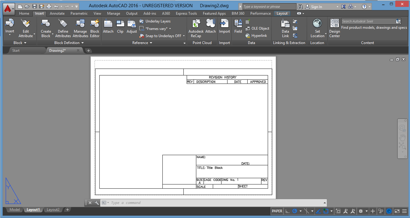
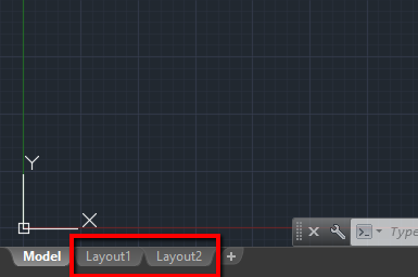
2. Open up a blank drawing and click on the “Layout” tab on the bottom left corner. As you can see by the looks of it, the Layout tab is used for the plotting stage of the production. Right click on the Layout 1 and select Page Setup Manager.

AutoCAD Layout Tabs

3. Click “Modify” and you will be presented with a pop up window. The most important thing you should pay attention to is the paper size. By default, this is set at (8.5 x 11 inches), so be sure to set it up so that it matches the size of the Title Block template.  Select “Landscape” on the Drawing Orientation panel and hit “OK”. We’re now ready to import the template.

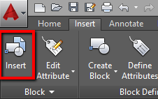
4. Click on the “Insert” tab and then on the “Insert” button on the far left side.

AutoCAD Insert Block Option

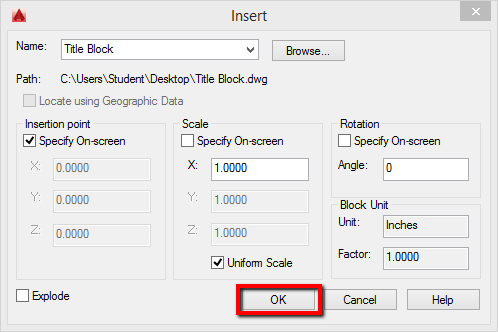
From the pop up menu, click on Browse and select your template. Leave the check boxes as they are – only check the “Specify on screen” box. Hit “OK”.

AutoCAD Title Block Dialog

5. Position the Title Block and left-click to put it in place. Note that the dashed line represents the print border, so keep in mind to position the Title Block within it.

From here you can further edit the individual Title Block elements by entering the “Block Editor” on the Insert tab. This can be extremely useful for repurposing existing title block templates and even customizing your own.

How To Trim Objects Quickly?

Part 12 of 13 in our How To Use AutoCAD series

Along with the many object manipulation features AutoCAD provides,  the Trim command is another common feature you’ll need to be familiar with as you modify your CAD drawings.

Trimming objects in AutoCAD is useful for merging objects at the place of their intersection.  The easiest way to trim objects in AutoCAD 2016 is to use the “Trim” command located on the Modify panel.

1.First, select the objects you want to trim. You can click on them individually or you can left click and drag to group the objects.

Trimming AutoCAD Objects

2.Right click on the blank space to finalize the selection.

3.Left click on the lines to trim them. Right click or enter to finalize the trimming.

Trimming AutoCAD Objects

Note that you can only trim the lines that intersect. The best tip for deleting unwanted lines would be to use the “Erase” command, which is also located on the Modify panel.

How To Place Horizontal And Vertical Dimensions Onto A Drawing?

AutoCAD Technical Design

Part 9 of 13 in our How To Use AutoCAD series

Placing dimensions in AutoCAD is essential for documenting your drawing. AutoCAD 2016 offers the same dimensions as the previous versions, that is: linear, aligned, angular, arc, radius, diameter, ordinate and jogged.

Using the “Linear” dimension command, you can create and place a horizontal, vertical or rotated dimension line.

You can accomplish this task by following these simple steps:

1.Locate the dimensioning tools in the Annotation panel, on the Home tab. Click on the drop-down arrow and choose “Linear”.  This will give us a horizontal or vertical distance between the selected points.

Locating AutoCAD Dimensioning Tools

2.Click on the snap points to specify the dimension line location.

3.Once you specify the dimension points, you have several choices: if you pull to the right, you’ll get horizontal measurement; if you pull upwards you’ll get vertical measurements.

4.Left click to complete the dimensioning and continue with your work.

In practice, you’ll probably have to create various dimensions, as well as utilize different dimension styles, depending on your project. For an all encompassing guide on using this AutoCAD feature check out CAD Tutor’s  AutoCAD Dimensioning Tutorial.

How To Quickly Create Perfectly Parallel Lines, Parallel Curves And Concentric Circles?

Part  8 of 13 in our How To Use AutoCAD series

While working in AutoCAD, you’ll often come across a situation where you need to draw perfectly parallel lines, rectangles or circles. Whether they’re for designing a structure, designing a machine part, or creating an object, precision is the goal.

Since it’s extremely important to be as accurate as possible when working on your drawings, the best way to quickly create perfectly parallel shapes is by using the “Offset” command.

The “Offset” command in AutoCAD 2016, is located on the bottom right of the Modify panel, on the Home tab.

Locating AutoCAD Offset Command

Here’s how to use the Offset command:

1.Draw a shape that you would like to offset.

2. Click on the Offset command (bottom right on the Modify panel).

3. Select the Offset distance. You can do this in two ways. The first is to enter the distance manually into the number box. The second way is to left click on a blank space in the drawing window and then move your cursor in any direction.

4. Select the object to offset. Left click on the object and you will get a perfectly parallel copy.

Using AutoCAD Offset


As a general rule of thumb, don’t forget to use Offset when drawing stairs, concentric circles or any other element. This command will save you a ton of time editing and re-adjusting your drawing by getting them right the first time around.

How To Align And Scale Objects Simultaneously?

Part 6 of 13 in our How To Use AutoCAD series

As you know, AutoCAD is all about creating accurate drawings. So being able to adjust and fine tune the placement and size of your objects accordingly is a necessary skill to have.  Whether you need to  resize your objects or move them around, you need to be able to manipulate your drawings accurately and with efficiency. That’s why it’s important to master the Align tool early on.

Here’s how to align and scale objects at the same time:

1. Identify which objects you would like to align. Go to the Modify panel, click on the drop down arrow and select the “Align” tool, located on the bottom left side.

Locating AutoCAD Align Tool

2. Select the object that you wish to align and hit “Enter”.

3. Select the source point. The source point is a part of the object that you align (for example, its edge, side or center). After doing so, specify the destination point of the alignment. The destination point represents a point to which you align your selected object. Hit “Enter” and specify the second source and destination point.

Specifying Second Destination Point

4. Either right click on the drawing window or press “Enter”. You’ll be prompted on whether you want to “Scale objects based on alignment points?” or not. If you’d like AutoCAD to automatically scale the selected object to fit your destination object, click Yes. Otherwise, click No.

Once you get the hang of it, this method will come as second nature. Mastering this tool is great skill to have under your belt. Not only does it allow you to quickly edit CAD designs accordingly, but it’ll also give you a better sense of how AutoCAD professionals work with the application.