How To Place Horizontal And Vertical Dimensions Onto A Drawing?

AutoCAD Technical Design

Part 9 of 13 in our How To Use AutoCAD series

Placing dimensions in AutoCAD is essential for documenting your drawing. AutoCAD 2016 offers the same dimensions as the previous versions, that is: linear, aligned, angular, arc, radius, diameter, ordinate and jogged.

Using the “Linear” dimension command, you can create and place a horizontal, vertical or rotated dimension line.

You can accomplish this task by following these simple steps:

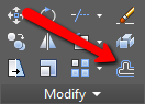
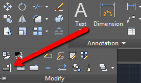
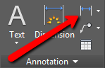
1.Locate the dimensioning tools in the Annotation panel, on the Home tab. Click on the drop-down arrow and choose “Linear”.  This will give us a horizontal or vertical distance between the selected points.

Locating AutoCAD Dimensioning Tools

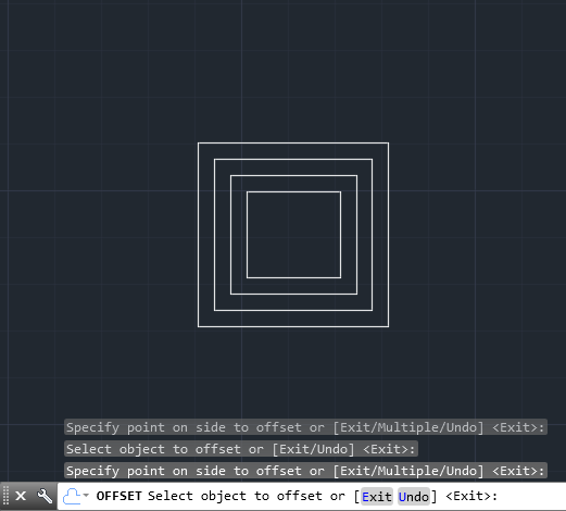
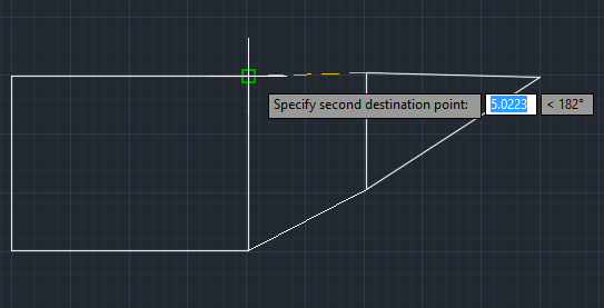
2.Click on the snap points to specify the dimension line location.

3.Once you specify the dimension points, you have several choices: if you pull to the right, you’ll get horizontal measurement; if you pull upwards you’ll get vertical measurements.

4.Left click to complete the dimensioning and continue with your work.

In practice, you’ll probably have to create various dimensions, as well as utilize different dimension styles, depending on your project. For an all encompassing guide on using this AutoCAD feature check out CAD Tutor’s  AutoCAD Dimensioning Tutorial.

How To Quickly Create Perfectly Parallel Lines, Parallel Curves And Concentric Circles?

Part  8 of 13 in our How To Use AutoCAD series

While working in AutoCAD, you’ll often come across a situation where you need to draw perfectly parallel lines, rectangles or circles. Whether they’re for designing a structure, designing a machine part, or creating an object, precision is the goal.

Since it’s extremely important to be as accurate as possible when working on your drawings, the best way to quickly create perfectly parallel shapes is by using the “Offset” command.

The “Offset” command in AutoCAD 2016, is located on the bottom right of the Modify panel, on the Home tab.

Locating AutoCAD Offset Command

Here’s how to use the Offset command:

1.Draw a shape that you would like to offset.

2. Click on the Offset command (bottom right on the Modify panel).

3. Select the Offset distance. You can do this in two ways. The first is to enter the distance manually into the number box. The second way is to left click on a blank space in the drawing window and then move your cursor in any direction.

4. Select the object to offset. Left click on the object and you will get a perfectly parallel copy.

Using AutoCAD Offset


As a general rule of thumb, don’t forget to use Offset when drawing stairs, concentric circles or any other element. This command will save you a ton of time editing and re-adjusting your drawing by getting them right the first time around.

How to Calculate CAD Scale Factor?

Industrial Technical Drawing

Part 7 of 13 in our How To Use AutoCAD series

When working in AutoCAD, you’re not only working with objects and drawings, you’re also working with dimensions and measurements. The latter two elements are what can make or break your drawing. If you can’t resize basic values when you need to, your drawings can’t be as accurate as needed.

Calculating a scale factor in CAD is, thus, a simple, but important task. When the drawings are printed for production, they’re represented much smaller than they actually are. Hence, we need to understand and implement the scale factors in order to adequately size dimensions, text, blocks and lines.

In short, the scale factor is the relationship between our printed units and our drawing units.  The simplest way to calculate the scale factor is by using these simple formulas.

For calculating scale factor out of architectural drawing scale:

  1. Choose your scale. For example:  1/4” = 1”
  2. Invert the fraction and multiply by 12 to get:  4/1 x 12 = 48
  3. Your scale factor is 48

For calculating the scale factor from an engineering drawing scale, only multiply the feet by 12. For an in-depth look at both engineering and architectural scales, check out this tutorial on CAD Scale Factors by ArchToolbox.

How To Align And Scale Objects Simultaneously?

Part 6 of 13 in our How To Use AutoCAD series

As you know, AutoCAD is all about creating accurate drawings. So being able to adjust and fine tune the placement and size of your objects accordingly is a necessary skill to have.  Whether you need to  resize your objects or move them around, you need to be able to manipulate your drawings accurately and with efficiency. That’s why it’s important to master the Align tool early on.

Here’s how to align and scale objects at the same time:

1. Identify which objects you would like to align. Go to the Modify panel, click on the drop down arrow and select the “Align” tool, located on the bottom left side.

Locating AutoCAD Align Tool

2. Select the object that you wish to align and hit “Enter”.

3. Select the source point. The source point is a part of the object that you align (for example, its edge, side or center). After doing so, specify the destination point of the alignment. The destination point represents a point to which you align your selected object. Hit “Enter” and specify the second source and destination point.

Specifying Second Destination Point

4. Either right click on the drawing window or press “Enter”. You’ll be prompted on whether you want to “Scale objects based on alignment points?” or not. If you’d like AutoCAD to automatically scale the selected object to fit your destination object, click Yes. Otherwise, click No.

Once you get the hang of it, this method will come as second nature. Mastering this tool is great skill to have under your belt. Not only does it allow you to quickly edit CAD designs accordingly, but it’ll also give you a better sense of how AutoCAD professionals work with the application.

How To Create Custom Hatch Patterns?

Part 5 of 13 in our How To Use AutoCAD series

One of the great things about AutoCAD is that it can be used to design drawings meant for different types of industries. And because AutoCAD designs can be intended for any structure under the sun, the material being used or involved in the design’s construction can vary greatly.  

This poses an interesting situation when AutoCAD users need to fill in the hatches of their drawings. These hatches represent the real material to be used. So getting the hatch patterns just as accurate as the drawings themselves is important.

Now, although AutoCAD offers plenty of hatch patterns on its own, sometimes we may want to personalize our drawings and implement our own hatch patterns. You can do this by following these simple steps:

1.In your AutoCAD document, draw a desired pattern using a tool from the Draw panel.

2. In the Block panel, click on the “Create” command, located in the top right corner.

Selecting Create Block Option

3. Name your pattern and click “OK”. On the pop-up, choose “Select objects”.

4. Click on your drawing until it gets light blue, and hit Enter.

5. Now select “Pick point” and place the cursor on the bottom left corner of your pattern drawing.

Selecting Pick Point Option

6. Hit “OK”.

7. Go to the “Express Tools” tab > Draw panel > Super Hatch.

Selecting Super Hatch

8. Choose “Block” as your desired pattern type, select your block by name and hit “OK”.

Selecting Hatch Pattern

9. Fit your pattern by following instructions. When you’re satisfied hit Enter.

10. Click on the desired area that you want to hatch and once selected, hit Enter.

All done! For advanced users who are interested in more hatch pattern customization options, check out this tutorial from Ellen Finkelstein.